 KELIBRON
 Measuring methods
How to Measure a Bore
To measure a bore with a caliper, put the inside jaws well into the hole, across the centre, and rock them gently for the largest reading; then repeat at 90°. Measure blind-hole depth with the depth rod, the beam end flat on the face.
On this page
Read the drawing first
Start from the feature and its tolerance: the bore size, its limits and how deep it must be measured (see the measurement plan). Example from the lab: the brass bushing bore is Ø28 +0.05/0, so any reading from 28.00 to 28.05 mm passes.
Measuring a through bore with a caliper
- Clean and zero: wipe the inside jaws and the bore, close the jaws and check the zero (ORIGIN on a digital caliper; see the vernier and dial caliper pages for their zero checks).
- Get the jaws in: insert the inside jaws as far as they go, square to the face, and open them until both touch the wall with light, even force.
- Across the centre: take the largest: rock the caliper gently sideways; off the centre line the jaws span a chord, which is shorter than the diameter.
- Along the axis: take the smallest: a caliper tilted along the bore spans a diagonal, which is longer than the diameter.
- Repeat in a second direction 90° away and near both ends of the bore; differences show out-of-round and taper.
On a caliper with separate knife-edge inside jaws the scale gives the bore directly; on models that measure bores with the outer faces of the lower jaws, add the jaw width marked on them.
Measuring blind-hole depth
Clear chips from the bottom first. Put the end of the beam flat on the reference face, push the depth rod down until it touches the bottom, keep it square to the face and read. A beam end that is not seated reads large; a chip on the bottom reads small.
Judging the bore against tolerance
Compare each reading with the limits (tolerances and fits). In the lab the 24-tooth gear has a bore of Ø20 +0.03/0 that reads 20.06 mm: above 20.03, so it is rejected. A blind hole specified 15 +0.05/0 deep that reads 14.93 mm is too shallow.
Common mistakes in a bore
| Wrong use | Reading |
|---|---|
| Jaws off the bore centre | Too small (chord) |
| Caliper tilted along the bore | Too large (diagonal) |
| Beam end not seated (depth) | Too large |
| Chip at the bottom (depth) | Too small |
| Zero not checked | Shifted by the zero error |
The lab demonstrates the first four on the bushing and the blind-hole part; zero error is shown on outside diameters and shifts an inside reading the same way.
When a caliper is not enough
Choose by the tolerance and the 10:1 rule (choosing instruments). The measurement plan uses a caliper for tolerances of about 0.2 mm or wider; tighter bores need an inside micrometer, a bore gauge or a plug gauge.
Two inside micrometers are in the lab: a 5–30 mm inside micrometer with measuring jaws, which reads the Ø28 bushing bore, and a 62–75 mm three-point bore micrometer, set on a Ø62 ring gauge. A three-point head centres itself in the bore, so it is easier to use than two-point contact (see types of micrometer).
Recording the result
Write each reading with the section and direction it was taken in, the instrument used and the decision, as in the measurement plan and the first article record.
Planned for the lab
Plug gauges, pin gauges, dial bore gauges, telescoping gauges, two-point inside micrometers and depth micrometers are not in the lab yet. Their shared basics — clean faces, a checked zero, a square position and light, even force — can be practised in the caliper bore scenes below.
References
- ISO 13385-1:2019 — Geometrical product specifications (GPS) — Dimensional measuring equipment — Part 1: Design and metrological characteristics of callipers · ISO
- JJG 30-2012《通用卡尺》检定规程 (cited by number; no public page) · 国家质量监督检验检疫总局
- GB/T 21389-2008《游标、带表和数显卡尺》 · 国家质量监督检验检疫总局、国家标准化管理委员会
- ISO 286-1:2010 — Geometrical product specifications (GPS) — ISO code system for tolerances on linear sizes — Part 1: Basis of tolerances, deviations and fits · ISO
- GB/T 1800.1-2020《产品几何技术规范(GPS)线性尺寸公差ISO代号体系 第1部分:公差、偏差和配合的基础》 (cited by number; no public page) · 国家市场监督管理总局、国家标准化管理委员会
- D. Flack, Callipers and Micrometers, NPL Measurement Good Practice Guide No. 40, Issue 2, 2014 (first issued 2001) · National Physical Laboratory
- JB/T 10006-2018《内测千分尺》 (cited by number; no public page) · 工业和信息化部
- GB/T 6314-2018《三爪内径千分尺》 · 国家市场监督管理总局、国家标准化管理委员会
Watch it done
Watch in the lab → Follow step by step →
Played back in the lab from domain commands; the reading and verdict come from the measurement model.
Practise in the lab
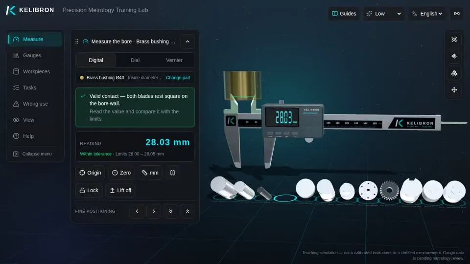 Digital caliperMeasure the bore of a bushingOpen in the lab →
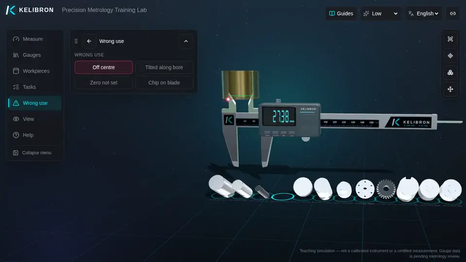 Digital caliper · wrong useWrong use: blades off the bore centreOpen in the lab →
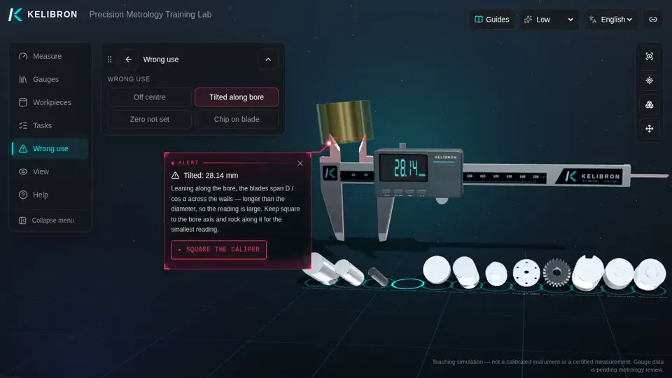 Digital caliper · wrong useWrong use: caliper tilted in a boreOpen in the lab →
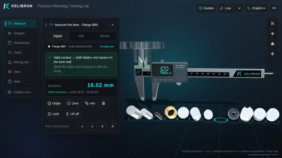 Digital caliperMeasure the bore of a flangeOpen in the lab →
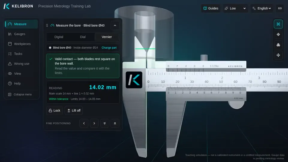 Vernier caliperVernier caliper: bore of a blind partOpen in the lab →
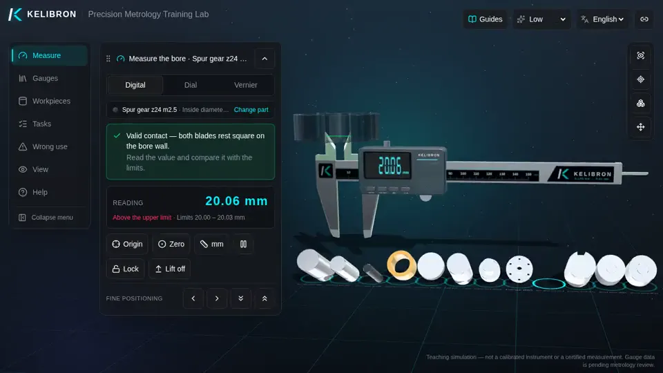 Digital caliperJudge a reamed-oversize gear bore (rejected)Open in the lab →
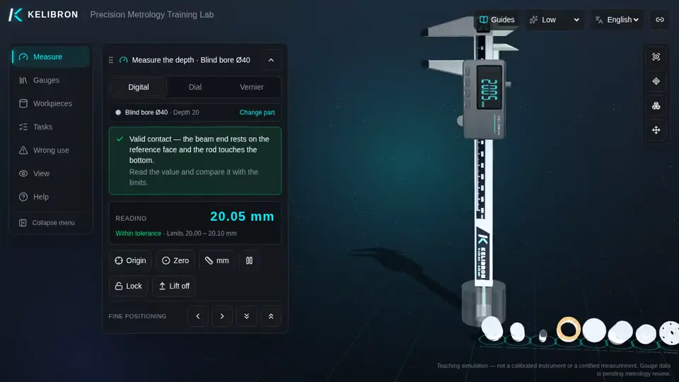 Digital caliperMeasure the depth of a blind boreOpen in the lab →
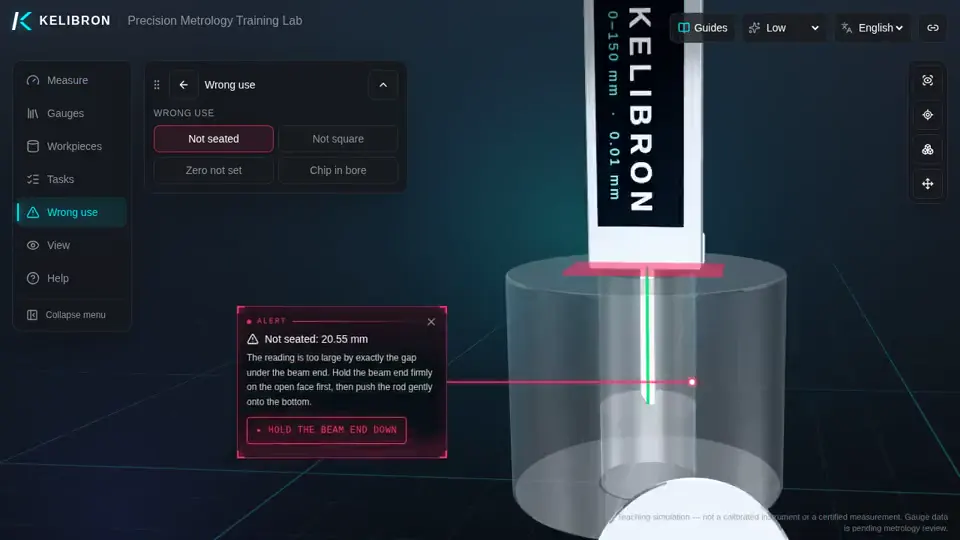 Digital caliper · wrong useWrong use: beam end not seated for depthOpen in the lab →
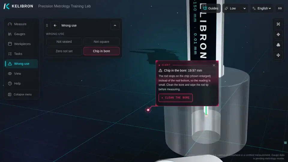 Digital caliper · wrong useWrong use: chips at the bottom of a blind boreOpen in the lab →
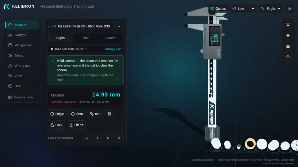 Digital caliperJudge a blind bore drilled short (rejected)Open in the lab →
- Inside micrometerRead a 5–30 mm inside micrometer on a Ø28 boreOpen in the lab →
- Three-jaw inside micrometerRead a three-jaw inside micrometer on a Ø62 ringOpen in the lab →
Questions
Which caliper jaws measure an inside diameter?
The inside jaws (the small jaws above the beam). Insert them fully, open until both touch, and rock for the largest reading.
Why rock the caliper for the largest reading?
Off the centre the jaws span a chord, which is shorter than the diameter, so the largest reading across the bore is the one through the centre.
Do I add the jaw width when measuring a bore?
Not with separate knife-edge inside jaws: they read directly. Only on models that measure bores with the outer faces of the lower jaws do you add the jaw width marked on them.
Try it yourself
Open the same setup in the 3D lab and take the reading yourself.
Related guides
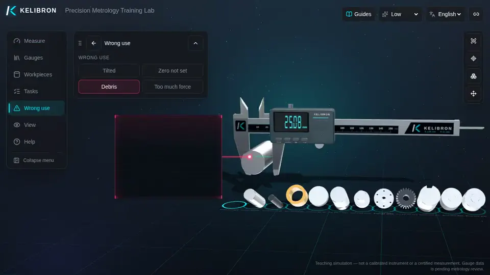 Measurement basicsMeasuring conditionsSizes on a drawing refer to 20 °C.
- Reading calipersLever test indicators and cosine errorWhen the stylus of a lever test indicator is tilted by an angle α from the correct direction, the true displacement is the reading times cos α: at 10° of tilt the gauge already reads about 1.5% high — so either square the stylus to the movement or correct the reading by cos α.
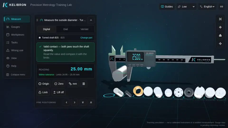 Measuring methodsHow to measure a machined partWork from the drawing, one feature at a time: what is the feature and its tolerance, which instrument has an error of about a tenth of that tolerance, how to hold the part and the instrument, where and how many times to measure, and how to record the result.