 KELIBRON
 Measuring methods
How to measure a machined part
Work from the drawing, one feature at a time: what is the feature and its tolerance, which instrument resolves about a tenth of that tolerance, how to hold the part and the instrument, where and how many times to measure, and how to record the result. A caliper covers most sizes with tolerances of about 0.2 mm and wider (down to about 0.1 mm only where a 4:1 ratio is accepted); tighter sizes need a micrometer, bore gauge or fixed gauge, and form and position tolerances need a reference surface and an indicator or a coordinate measuring machine.
On this page
Five steps
- Read the drawing: list every characteristic with its nominal size, tolerance and datum; number them (see first article inspection).
- Pick the instrument: its error should be about a tenth of the tolerance band (4:1 or 3:1 when that is not possible) — a rule of thumb, not a standard requirement; see choosing instruments.
- Choose the method: contact points, how to hold the part, which datum to measure from, how to avoid tilt.
- Decide where and how often: several positions along and around the feature to catch taper and out-of-round.
- Record actual values, the instrument used and the decision.
Common features and what to use
| Feature | Tolerance about 0.2 mm or wider | Tighter tolerances | Method notes |
|---|---|---|---|
| Outside diameter | Caliper | Micrometer; snap gauge | Part deep in the jaws, square; several positions, two directions |
| Bore | Caliper inside jaws | Bore gauge, internal micrometer; plug gauge | Maximum across, minimum along the axis |
| Depth, step height | Caliper depth rod or step | Depth micrometer; height gauge on a surface plate | Beam end flat on the reference face |
| Hole centre distance | Caliper over / inside the holes | Height gauge, CMM | C = L − (d₁ + d₂)/2 or L + (d₁ + d₂)/2 |
| Keyway width and depth | Caliper | Gauge blocks or keyway gauges; micrometer or blade micrometer from the keyway bottom to the opposite side | Depth measured from the opposite side of the shaft |
| Thread | Pitch gauge (identifies the pitch only, no conformity check) | Thread plug / ring gauges; thread micrometer; three-wire method | Go / no-go thread gauges decide conformity (go: functional size; no-go: pitch diameter) |
| Roundness, runout, flatness | Not with a caliper: dial indicator on V-blocks, between centres or on a surface plate; form tester or CMM | Define the datum first | |
Where to measure and how often
A single reading hides taper, out-of-round and burrs. On a shaft measure at both ends and the middle, each in two directions at 90°; on a bore do the same at the top and the bottom. For series production, the control plan sets the sample size and frequency; first article and patrol checks follow your procedure.
When a caliper is not enough
A caliper cannot check form or position tolerances, cannot measure narrow grooves or deep small bores, and is too coarse for tolerances under about 0.1–0.2 mm. If you cannot find a method, ask for the drawing’s datum scheme, look for a fixed gauge (plug, ring, snap, thread gauge) or a fixture, or send the part to a measuring room with a CMM.
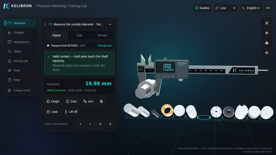
In KELIBRON you can practise the outside-diameter, bore and depth rows on real-sized parts: shafts, a stepped shaft, a keyway shaft (outside diameter), a flange, a bushing, a gear and blind bores.
References
- ISO 14253-1:2017 — GPS — Inspection by measurement of workpieces and measuring equipment — Part 1: Decision rules for verifying conformity or nonconformity with specifications · ISO
- ISO 286-1:2010 — Geometrical product specifications (GPS) — ISO code system for tolerances on linear sizes — Part 1: Basis of tolerances, deviations and fits · ISO
Watch it done
Played back in the lab from domain commands; the reading and verdict come from the measurement model.
Practise in the lab
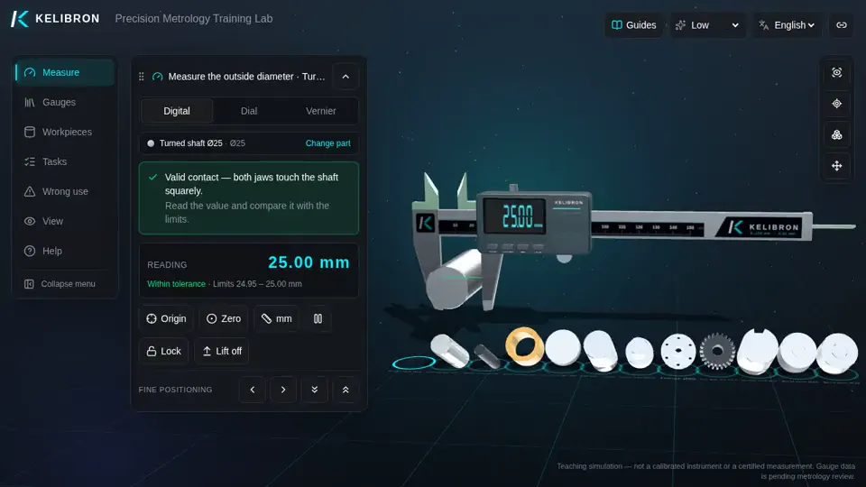 Digital caliperMeasure a Ø25 shaftOpen in the lab →
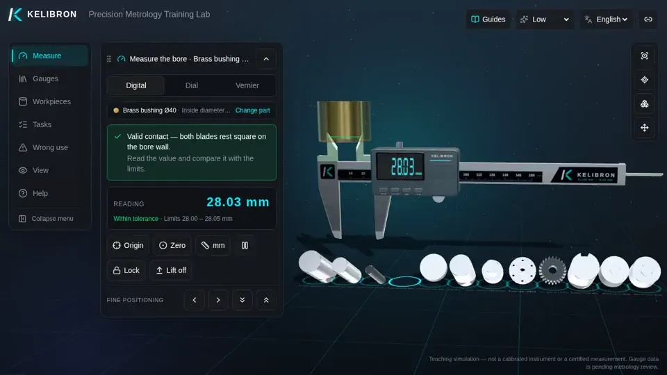 Digital caliperMeasure the bore of a bushingOpen in the lab →
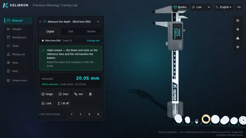 Digital caliperMeasure the depth of a blind boreOpen in the lab →
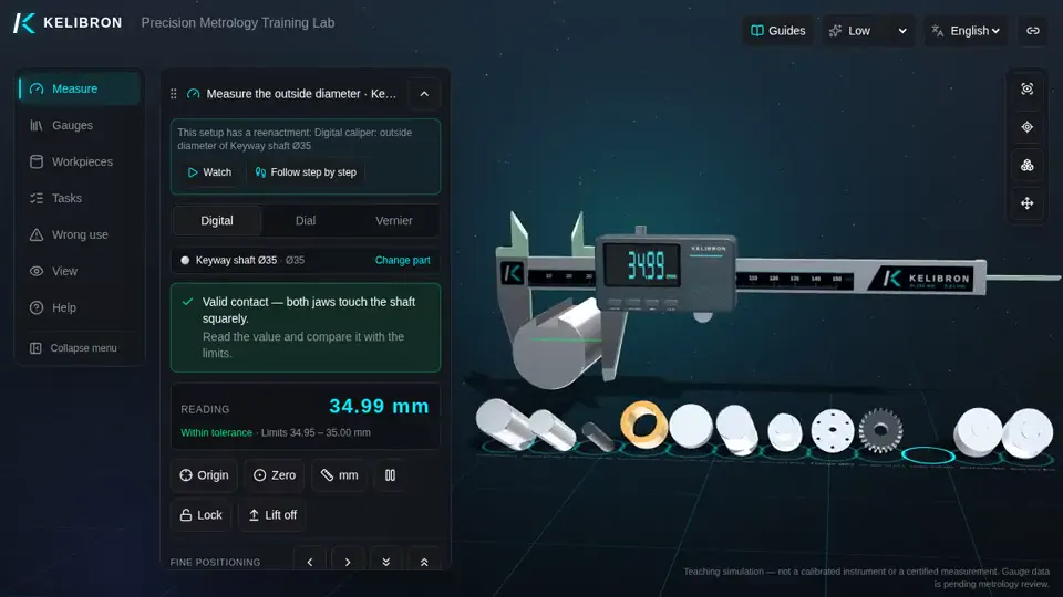 Digital caliperMeasure a Ø35 keyway shaftOpen in the lab →
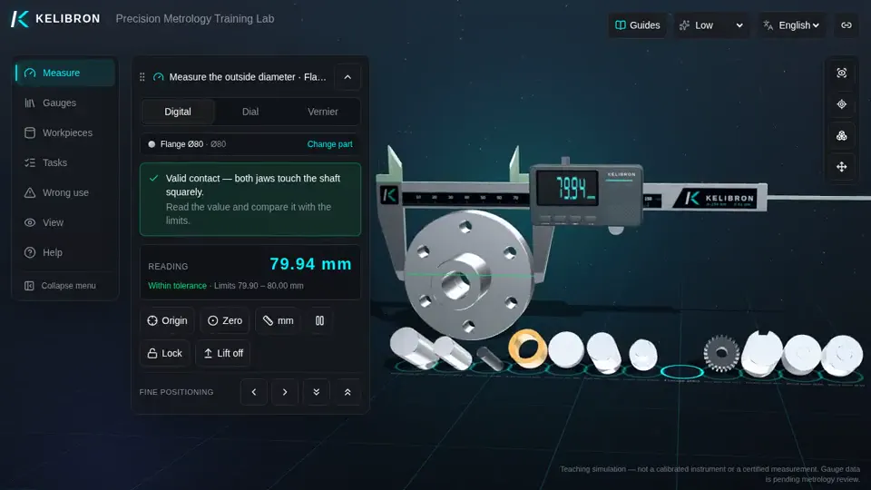 Digital caliperMeasure the outside diameter of a flangeOpen in the lab →
Questions
How do I decide which instrument to use?
Start from the tolerance band: choose an instrument whose error is about a tenth of it (at least a third), that can reach the feature and that is calibrated.
Can I measure roundness with a caliper?
No. Comparing diameters in two directions only shows ovality roughly; roundness needs a dial indicator on V-blocks or between centres, or a form tester.
Try it yourself
Open the same setup in the 3D lab and take the reading yourself.
Related guides
- Measuring methodsMeasuring common partsMeasure every diameter at several places along the part and in two directions 90° apart; the spread reveals taper and out-of-round.
- Measuring methodsFirst article inspection and the inspection recordA first article inspection checks the first part from a new or changed setup against the drawing requirements your procedure names — all of them for a full first article inspection — before production continues.
 Measuring methodsSteps, hole-to-edge and centre distanceA caliper cannot touch a hole centre, so centre distances are calculated: across the far edges of two holes C = L(outer) − (d1 + d2)/2; across the near edges C = L(inner) + (d1 + d2)/2.