 KELIBRON
 Measuring methods
Measuring common parts
Measure every diameter at several places along the part and in two directions 90° apart; the spread reveals taper and out-of-round. Record each value and judge against the drawing limits.
On this page
Shaft
Measure each diameter near both ends and in the middle, each time in two directions 90° apart. Differences along the length show taper; differences between directions show out-of-round (a caliper only gives a rough idea — use a micrometer or V-block and indicator for form).
Bushing
Outside diameter with the outside jaws, bore with the inside jaws (maximum across the bore, minimum along the axis), length, and depth of any counterbore. Wall thickness ≈ (D − d)/2 only when bore and outside are concentric; otherwise measure the wall directly at several points.
Flange
Outside diameter, bore, thickness, spigot diameter and height, and the bolt holes: their diameter and the pitch-circle diameter: with an even number of holes it equals the centre distance between opposite holes; with an odd number n, PCD = c / sin(180°/n), where c is the centre distance of adjacent holes.
Gear tip diameter
With an even number of teeth, measure across opposite tips. With an odd number, opposite a tip lies a gap, so measure the radial height H from the bore wall to a tip and compute da = dbore + 2H. For a standard spur gear da = m(z + 2), which gives an estimate of the module m.
Blind hole
Bore diameter near the mouth and as deep as the jaws reach; depth with the beam end flat on the face and the rod square, after clearing chips from the bottom.
References
- ISO 13385-1:2019 — Geometrical product specifications (GPS) — Dimensional measuring equipment — Part 1: Design and metrological characteristics of callipers · ISO
- ISO 286-1:2010 — Geometrical product specifications (GPS) — ISO code system for tolerances on linear sizes — Part 1: Basis of tolerances, deviations and fits · ISO
Watch it done
Played back in the lab from domain commands; the reading and verdict come from the measurement model.
Practise in the lab
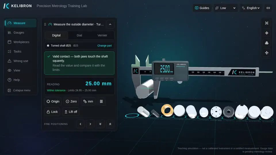 Digital caliperMeasure a Ø25 shaftOpen in the lab →
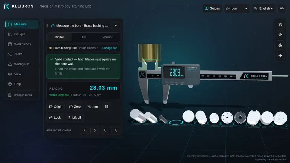 Digital caliperMeasure the bore of a bushingOpen in the lab →
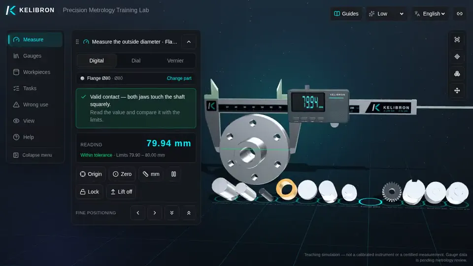 Digital caliperMeasure the outside diameter of a flangeOpen in the lab →
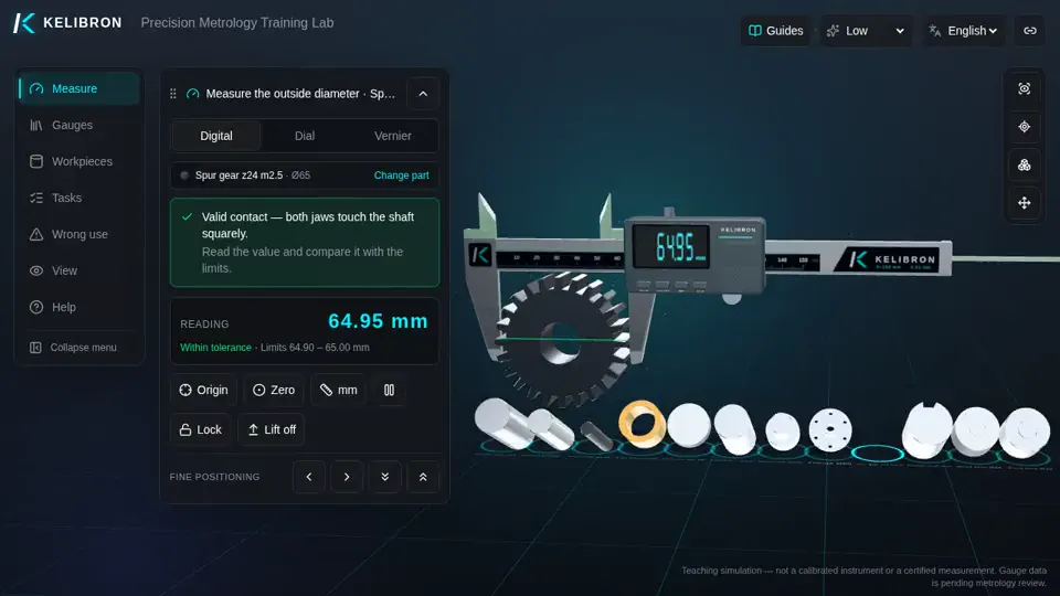 Digital caliperMeasure the tip diameter of a 24-tooth gearOpen in the lab →
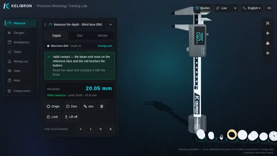 Digital caliperMeasure the depth of a blind boreOpen in the lab →
Questions
Why measure a shaft in two directions?
A shaft can be slightly oval; measuring 90° apart shows the difference. The diameter is judged on each measured value.
How do I measure the outside diameter of a gear with an odd number of teeth?
Measure from the bore wall to a tip (H) and use d_a = d_bore + 2H, or use a dedicated method; across the teeth a caliper reads low.
Try it yourself
Open the same setup in the 3D lab and take the reading yourself.
Related guides
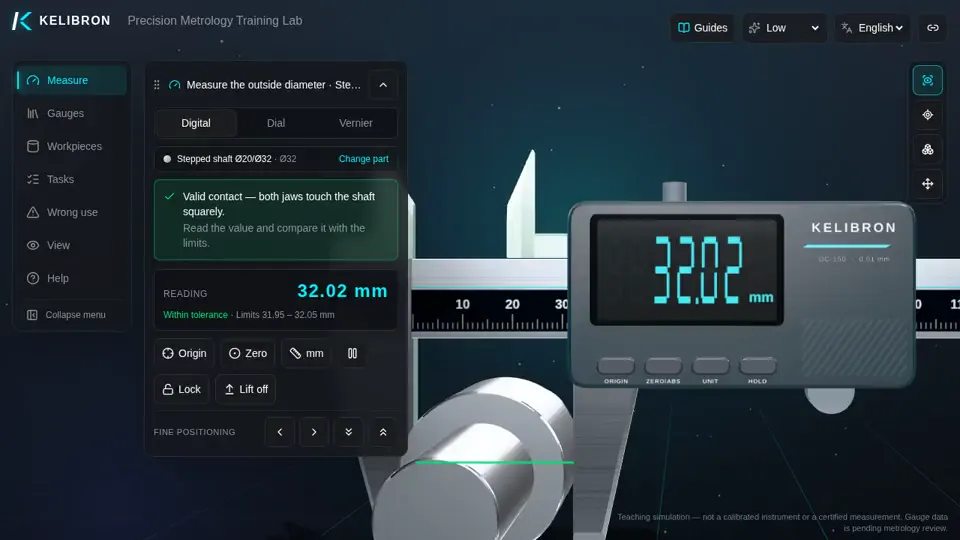 Measuring methodsSteps, hole-to-edge and centre distanceA caliper cannot touch a hole centre, so centre distances are calculated: across the far edges of two holes C = L(outer) − (d1 + d2)/2; across the near edges C = L(inner) + (d1 + d2)/2.
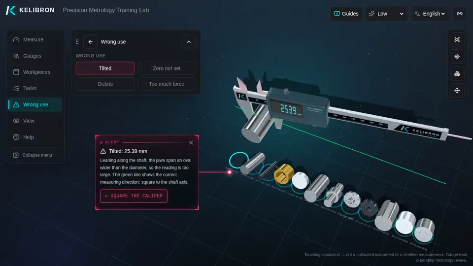 Measuring methodsCaliper measurement errors and how to avoid themMost wrong caliper readings come from the setup, not the instrument: an unchecked zero, a tilted caliper, dirt, too much force, parallax or measuring far from the beam.
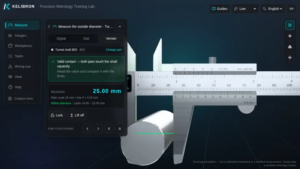 Reading calipersHow to read and use a caliperCheck zero with the jaws closed, hold the part deep in the jaws and square to the beam, close with light, even force, then read: on a vernier, the main-scale millimetres plus the coinciding line × 0.02 mm; on a dial, millimetres plus the needle’s hundredths; on a digital caliper, the display.