 KELIBRON
 Reading calipers
Lever test indicators and cosine error
When the stylus of a lever test indicator is tilted by an angle α from the correct direction, the true displacement is the reading times cos α: at 10° of tilt the gauge already reads about 1.5% high — so either square the stylus to the movement or correct the reading by cos α.
On this page
How it works and when to use it
A lever test indicator has a short stylus that pivots around a bearing; its movement is amplified by gears and shown by a pointer on a circular scale. It reads a difference, so it is a comparative measuring instrument — this is the definition given in ISO 9493.
A plunger dial indicator must stand with its plunger along the measured displacement. A lever indicator reads displacement in the direction normal to the stylus axis, so the body can lie on its side: clamped in a stand it compares parts along a horizontal direction, checks geometry, and sets up machine tools (ISO 9493, types S, H and V; Modern Machine Shop).
The common division value is 0.01 mm; 0.001 mm and 0.002 mm indicators are also made — the scale examples in ISO 9493 list exactly these three intervals. The stylus can be displaced in either direction from its rest position; some indicators have a bias lever to switch direction. The body clamps to a stand by its dovetail (ISO 9493).
Cosine error
Used correctly, the stylus axis lies parallel to the workpiece surface and the measured displacement is normal to it. Tilt the stylus by an angle α and the pointer shows only the component of the displacement normal to the stylus axis: true displacement = reading × cos α, so the reading is always larger than the truth. ISO 9493 states that if the indicator is used at another angle, a correction shall be made.
| Tilt α | Correction cos α | Reading is high by |
|---|---|---|
| 10° | 0.985 | about 1.5% |
| 20° | 0.94 | about 6% |
| 30° | 0.87 | about 15% |
| 40° | 0.77 | about 31% |
Example: tilted 30°, the indicator reads 0.12 mm. True displacement = 0.12 × cos 30° = 0.104 mm — a difference of 0.016 mm that can flip a tolerance decision.
Setting up to avoid the error
The simplest solution is geometric: swing the stylus until it is square to the movement — the friction clutch at the pivot holds it there even when the body itself stands at an angle. Mitutoyo’s guidance is to keep the tilt under 10°, where the coefficient 0.985 makes the effect negligible.
When there is no room to square up, some makers supply involute (pear-shaped) tips that correct the error automatically over a limited angle — the published ranges differ (Modern Machine Shop: up to about 20° from parallel; a Brown & Sharpe distributor: up to 36°, with Interapid and Bestest designed for a 12° stylus offset), so follow the maker’s own note. With an ordinary ball tip you must correct by cos α yourself.
Do not fit a stylus of a different length: a longer tip makes the gauge less sensitive to linear displacement and a shorter one more sensitive, changing the reading relationship. Replace like with like, at the standard length.
Standards
In China, lever indicators are covered by GB/T 8123-2007 Dial lever indicators (current); internationally by ISO 9493:2010, confirmed in 2021.
Planned for the lab
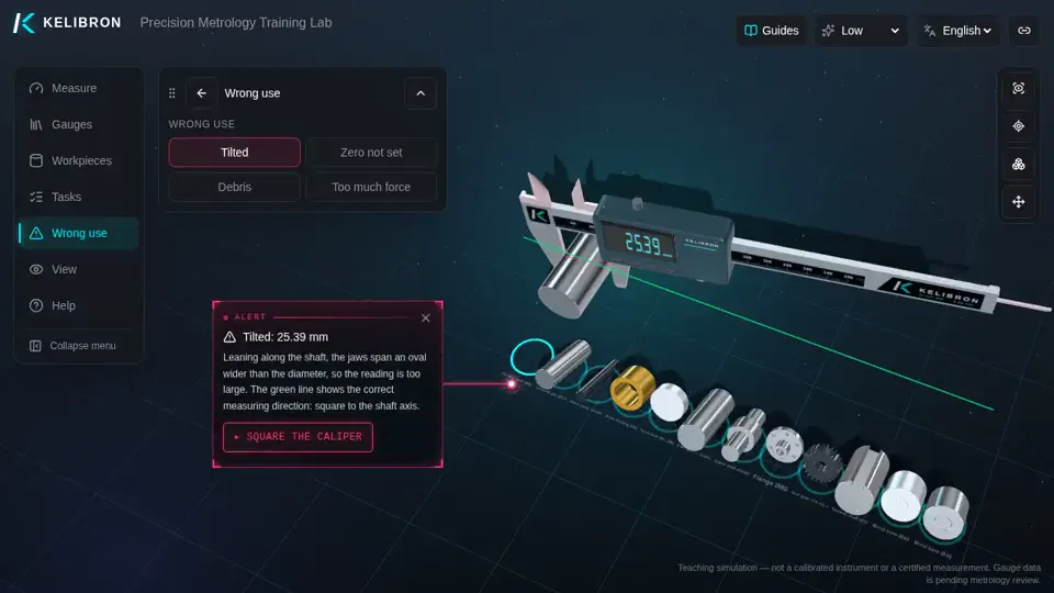
Lever test indicators are planned for KELIBRON (intake group G2). Until then, practise the shared habit on the caliper scenes below: square the gauge to the measurement before reading — the tilt scenario shows what happens when you do not.
References
- ISO 9493:2010 — Geometrical product specifications (GPS) — Dimensional measuring equipment: Dial test indicators (lever type) — Design and metrological characteristics (confirmed 2021) · ISO
- GB/T 8123-2007《杠杆指示表》 · 国家质量监督检验检疫总局、国家标准化管理委员会
- Mitutoyo, “Check Points — Lever type dial test indicators” (E12024-US) · Mitutoyo
- C. Yost, “What’s wrong with my test indicator? A cosine error discussion”, The Gaging Store (Brown & Sharpe / Hexagon distributor) · The Gaging Store
- “How to Correct for Cosine Error”, Modern Machine Shop · Modern Machine Shop
Practise the shared basics on a caliper
Questions
What is the difference between a lever indicator and a dial indicator?
A dial indicator has a plunger that must point along the measured displacement; a lever indicator has a pivoting stylus and reads displacement normal to the stylus axis, so the body can lie sideways — useful where a plunger cannot reach or on a surface plate. Both read differences, not absolute sizes.
Does cosine error make the reading too high or too low?
Too high: reading = true displacement / cos α, and the error grows with the tilt — about 1.5% at 10°, 6% at 20° and 15% at 30°.
At what tilt must I correct the reading?
Mitutoyo’s guidance: under 10° the effect can be ignored; beyond that, correct with true displacement = reading × cos α, or use an involute tip within the range the maker states.
Practise the basics first
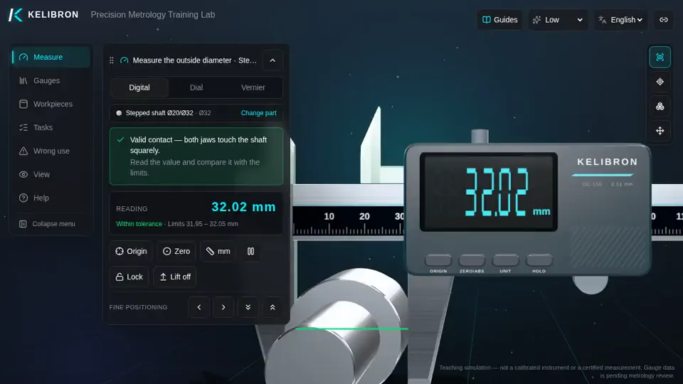
Cleaning, zero checks, square positioning, light even force and reading to the scale interval are the same on every instrument; practise them in a caliper scene.
Related guides
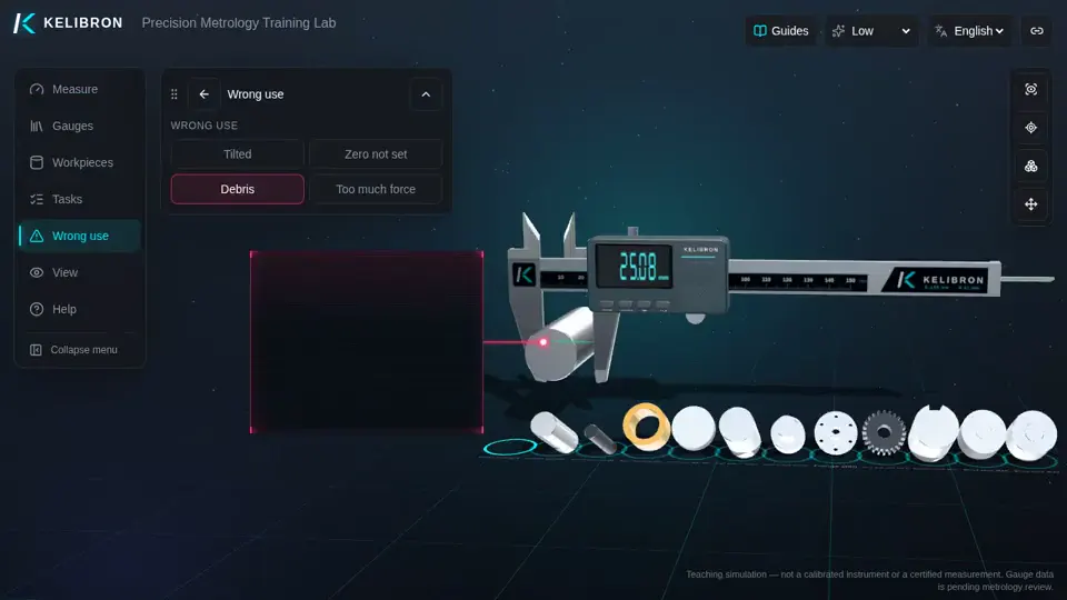 Measurement basicsMeasuring conditionsSizes on a drawing refer to 20 °C.
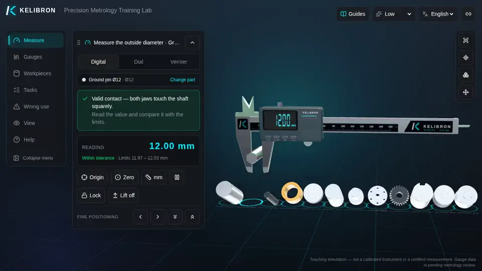 Measurement basicsRecording readingsWrite a reading with every digit the instrument resolves, trailing zeros included, and with its unit.
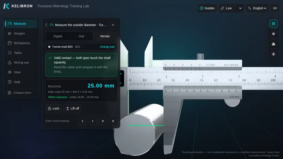 Reading calipersHow to read and use a caliperCheck zero with the jaws closed, hold the part deep in the jaws and square to the beam, close with light, even force, then read: on a vernier, the main-scale millimetres plus the coinciding line × 0.02 mm; on a dial, millimetres plus the needle’s hundredths; on a digital caliper, the display.