 KELIBRON
 Measuring methods
Finding the inspection characteristics on a drawing
An inspection characteristic is a requirement on the drawing that the part must meet and that someone has to check: a size with its tolerance, a size that takes the general tolerance, a geometric tolerance, a surface texture requirement, or a note that sets a requirement, plus any requirement added by the purchase order. Give each one a number, write down its limits, and the list becomes the starting point of the measurement plan and of the inspection record.
On this page
What counts as a characteristic?
- Sizes with a tolerance, such as Ø20 0/−0.05.
- Sizes without a tolerance: they take the general tolerance named in or near the title block (see reading sizes on a drawing).
- Geometric tolerances: form, orientation, location and run-out, each in its own frame (GB/T 1182, ISO 1101).
- Surface texture requirements, such as an Ra value on a surface symbol.
- Notes that set a requirement, such as “remove burrs and break sharp edges”, a material or a heat treatment.
- Requirements added by the purchase order or by a specification the drawing invokes.
Reference dimensions, usually shown in parentheses, and basic (theoretically exact) dimensions are for information or show a relationship; IAQG’s first article guidance classes both as reference characteristics, not requirements to judge. A basic dimension is not checked on its own; the tolerance zone it locates is judged through the geometric tolerance. Some customers still ask for them to be numbered and measured; follow the customer’s procedure.
Numbering the drawing (ballooning)
Give every requirement a unique number, usually written in a circle next to it on a copy of the drawing; this is the ballooned or bubbled drawing. The IAQG guidance on AS9102 does not prescribe a method or make a ballooned drawing mandatory: any technique works as long as each requirement can be traced from the drawing to its result.
Number in a fixed order, for example zone by zone or view by view, so that a second person can check that nothing was missed.
From the drawing to a characteristic list
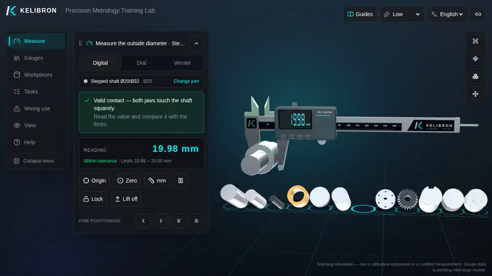
For each number, write what is required and work out the limits. The stepped shaft from the KELIBRON lab gives this list:
| No. | Characteristic | Requirement | Lower limit (mm) | Upper limit (mm) |
|---|---|---|---|---|
| 1 | Small diameter | Ø20 0/−0.05 | 19.95 | 20.00 |
| 2 | Large diameter | Ø32 ±0.05 | 31.95 | 32.05 |
| 3 | End diameter | Ø20 0/−0.05 | 19.95 | 20.00 |
| 4–6 | Lengths 30, 22, 30 | No tolerance given (on a drawing: the general tolerance in the title block) | not given in the lab | |
The next step, choosing an instrument and the measuring points for each line, is the measurement plan; the same numbers then head the columns of the first article record.
Key and critical characteristics
Some drawings mark characteristics with designators such as key, critical, major or minor. The design authority defines what each mark means in its engineering documents; the first article standard does not.
IAQG’s overview of AS9103 quotes the 2001 AS9100 definition: a key characteristic is a feature of a material or part whose variation has a significant influence on fit, performance, service life or manufacturability. AS9103 (current edition AS9103B, 2022) sets how that variation is managed in production. For the inspector, a marked characteristic carries whatever extra requirement the customer attaches to the mark, such as variation data under AS9103.
Practising in KELIBRON
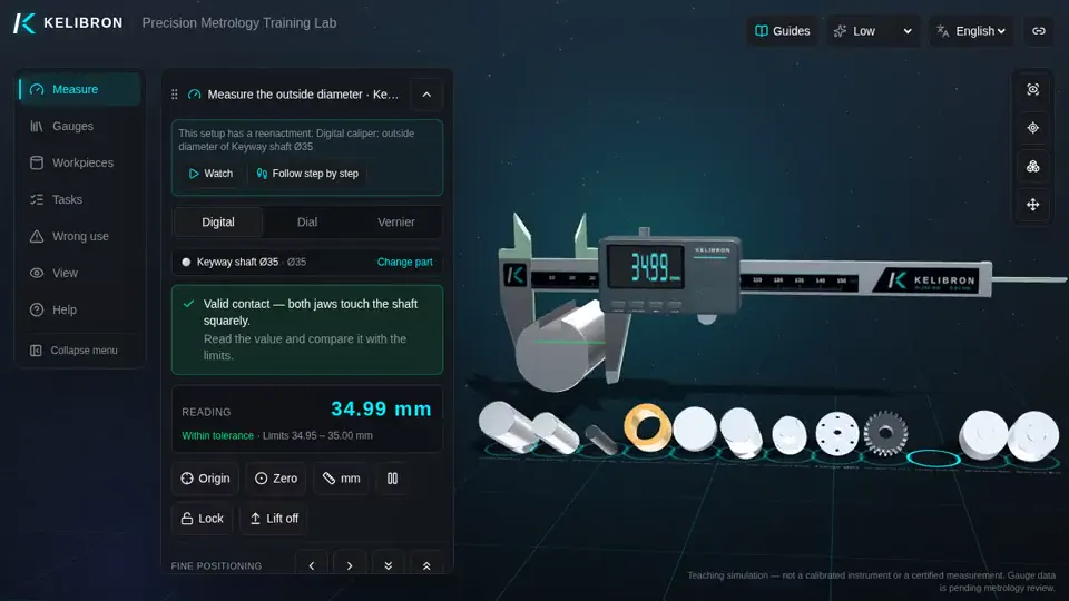
The part list gives each part’s drawing size and deviations, and the panel shows the limits under the reading. On the stepped shaft, measure characteristics 1–3 from the list above: characteristic 3 is made at 20.01 mm, above its 20.00 upper limit, so it is a reject. The lengths carry no tolerance in the lab and are not judged. On the keyway shaft the lab gives a tolerance only for the outside diameter, Ø35 0/−0.05; on a real drawing the keyway width and depth would be characteristics as well. On a real part, close the jaws across the round, not into the slot.
References
- IAQG — First Article Inspection 9102B Updated FAQs (19 February 2015; guidance incorporated into 9102C and the SCMH) · International Aerospace Quality Group
- IAQG — AS9103 Overview: Variation Management of Key Characteristics (presentation on the 2001 edition; current edition AS9103B, 2022) · International Aerospace Quality Group
- SAE AS9102 — Aerospace First Article Inspection Requirement (cited by number; no public page) · SAE International
- GB/T 1182-2018《产品几何技术规范(GPS) 几何公差 形状、方向、位置和跳动公差标注》 · 国家市场监督管理总局、国家标准化管理委员会
- ISO 1101:2017 — Geometrical product specifications (GPS) — Geometrical tolerancing — Tolerances of form, orientation, location and run-out (confirmed 2022) · ISO
- GB/T 1804-2000《一般公差 未注公差的线性和角度尺寸的公差》 · 国家质量技术监督局
- ISO 2768-1:1989 — General tolerances — Part 1: Tolerances for linear and angular dimensions without individual tolerance indications · ISO
How the guides are checked against these sources: About KELIBRON.
Watch it done
Watch in the lab → Follow step by step →
Played back in the lab from domain commands; the reading and verdict come from the measurement model.
Practise in the lab
Questions
Do reference dimensions need to be inspected?
Not as a requirement: a reference dimension is for information only. Some customers still ask for it to be numbered and measured, so follow their procedure.
Is a ballooned drawing required for a first article inspection?
The IAQG guidance on AS9102 says it is not required; any method that traces each requirement to its result is acceptable. A ballooned drawing is a common way to show that.
Who decides which characteristics are key?
The design authority, in the drawing or the engineering documents that define the marks.
Try it yourself
Open the same setup in the 3D lab and take the reading yourself.
Related guides
 Measuring methodsHow to measure a machined partWork from the drawing, one feature at a time: what is the feature and its tolerance, which instrument has an error of about a tenth of that tolerance, how to hold the part and the instrument, where and how many times to measure, and how to record the result.
- Measuring methodsMeasuring common partsMeasure every diameter at several places along the part and in two directions 90° apart; the spread reveals taper and out-of-round.
 Measuring methodsFirst article inspection and inspection recordA first article inspection checks the first part from a new or changed setup against the drawing requirements your procedure names (all of them for a full first article inspection) before production continues.